This is how you wire the Game Boy Controller v2.1 and v2.2.
Latest version v2.1.01/v2.2: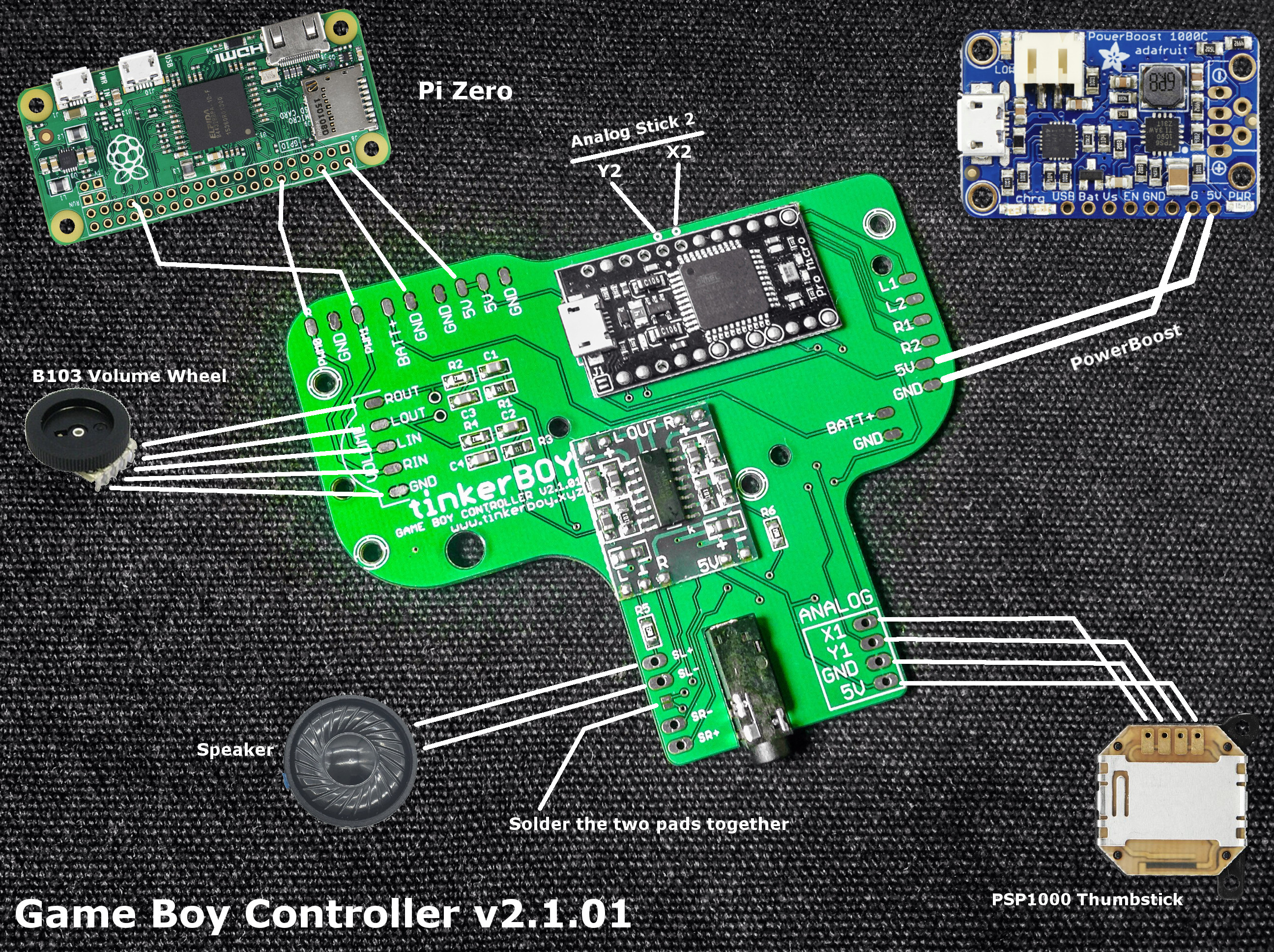
Previous version v2.1: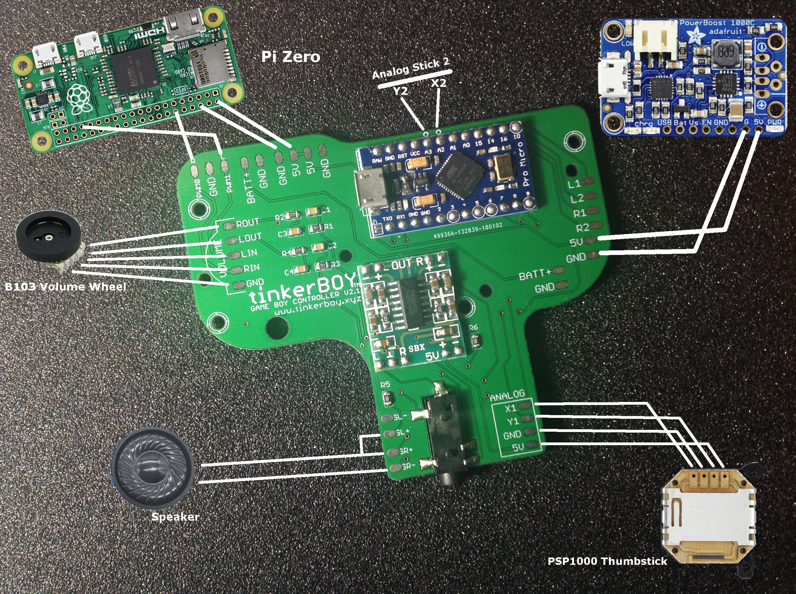
>> How To Wire The Micro USB 4-Wire Data Cable.
Additional Parts You May Need:
-
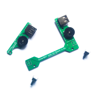
tinkerBOY Add-On Board – with Pre-soldered USB Type A Port and 3-Pin Volume Wheel, Back Buttons
Select options This product has multiple variants. The options may be chosen on the product page -
tinkerBOY Speaker 4Ω2W / 8Ω1W
Select options This product has multiple variants. The options may be chosen on the product page -
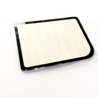
Game Boy Zero Glass Screen Cover Protector
Select options This product has multiple variants. The options may be chosen on the product page -
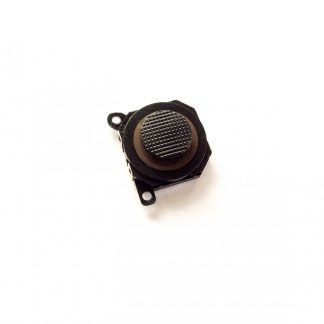
PSP1000 Analog Stick
Read more -
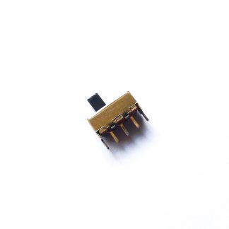
SPDT Slide Switch 1P2T for Game Boy Zero
Add to cart -
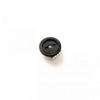
B103 Volume Wheel 10K Ohm 5Pin Double Dial Taper
Read more -
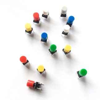
Momentary Push Button Tactile Switches with Caps (2pcs, 6x6x10mm)
Select options This product has multiple variants. The options may be chosen on the product page -
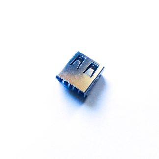
USB Female Type A 4-Pin Socket/Port
Add to cart -
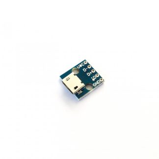
Micro USB micro-B Breakout Board
Add to cart
When there is a drilling pattern for 6 buttons?
I have uploaded a 6-button pdf template you can print. Just make sure you print it in its actual size. So if you’re printing from Chrome browser make sure you uncheck the option “Fit to page”.
Download at: https://www.tinkerboy.xyz/wp-content/uploads/2018/08/tinkerBOY_6-BUTTON_TEMPLATE.pdf
I like also to have template to drill six buttons.
I have uploaded a 6-button pdf template you can print. Just make sure you print it in its actual size. So if you’re printing from Chrome browser make sure you uncheck the option “Fit to page”.
Download at: https://www.tinkerboy.xyz/wp-content/uploads/2018/08/tinkerBOY_6-BUTTON_TEMPLATE.pdf