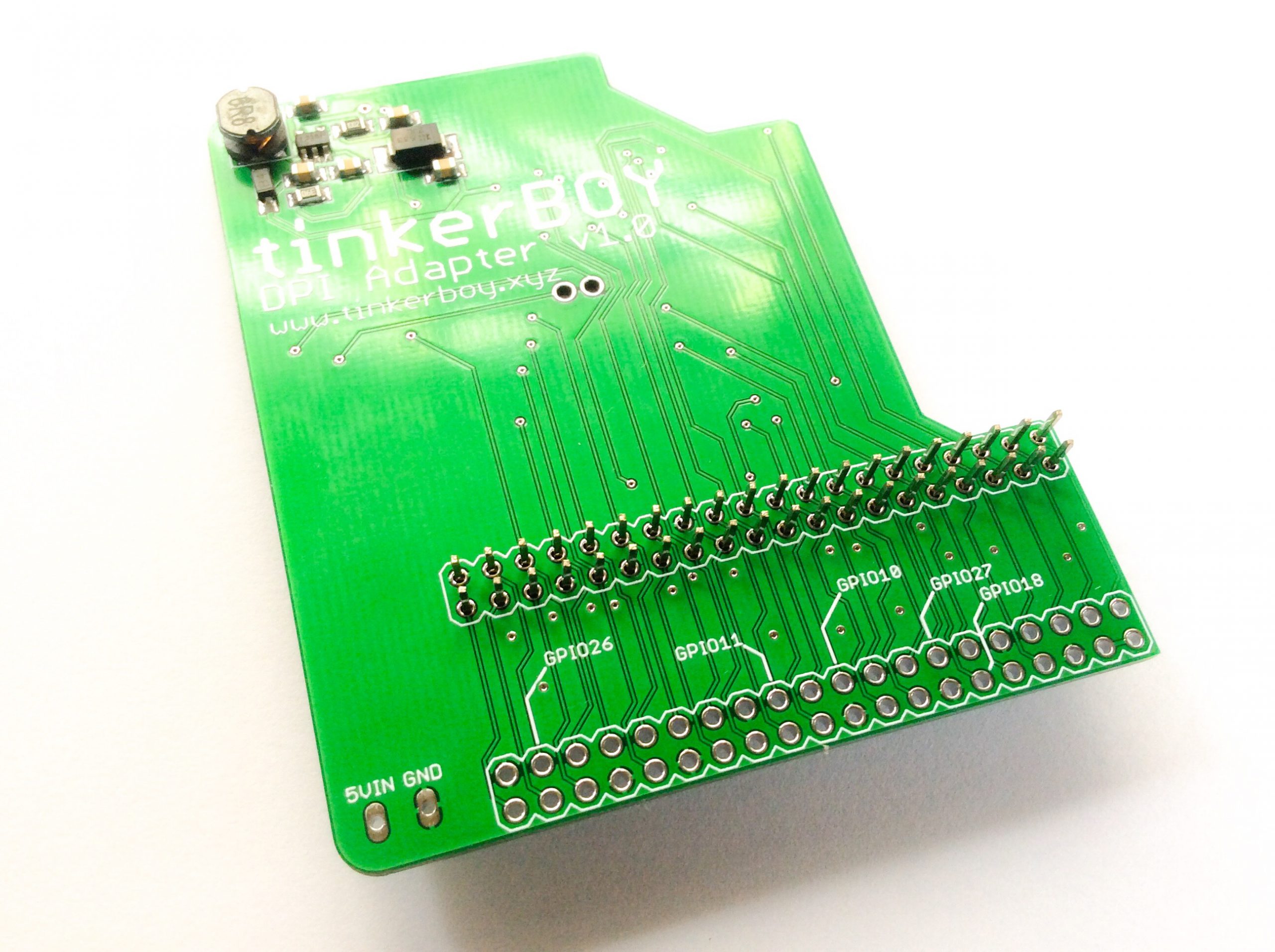
Start by placing the header pins in to the pin holes designed for the Pi Zero:
And mount the Pi Zero this way: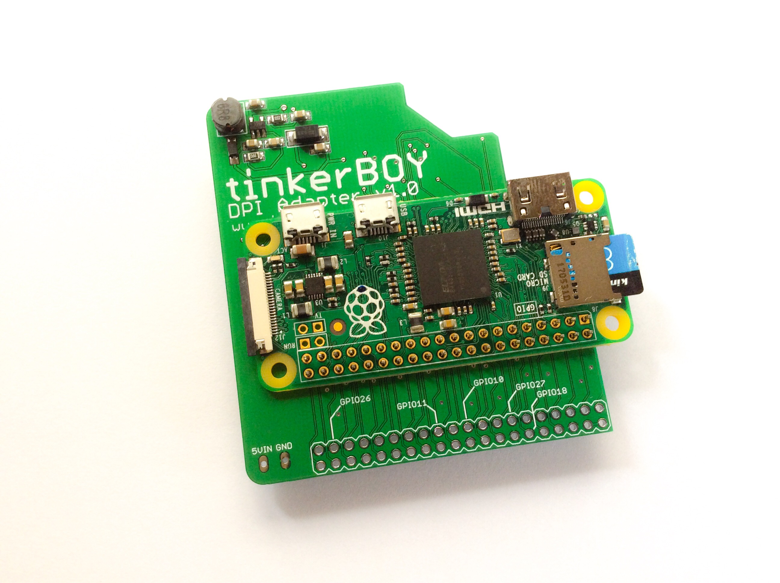
It’s recommended to put a kapton tape or anything in between the adapter and pi zero to avoid shorts before soldering the header pins to the Pi.
The next step is to cut the pins and plastic below the header pins and solder them to the DPI Adapter.
The final step is to solder the Pi Zero’s USB data pins (D+ and D-) to the 2 holes on the DPI Adapter. These holes will connect the Pi Zero’s data pins to the D+ and D- pads on the adapter for connecting any USB device. (Note: The D+ and D- pads on the DPI board are mislabeled. The upper pad should be D- and the lower pad should be D+. Thanks to Paul for reporting.)
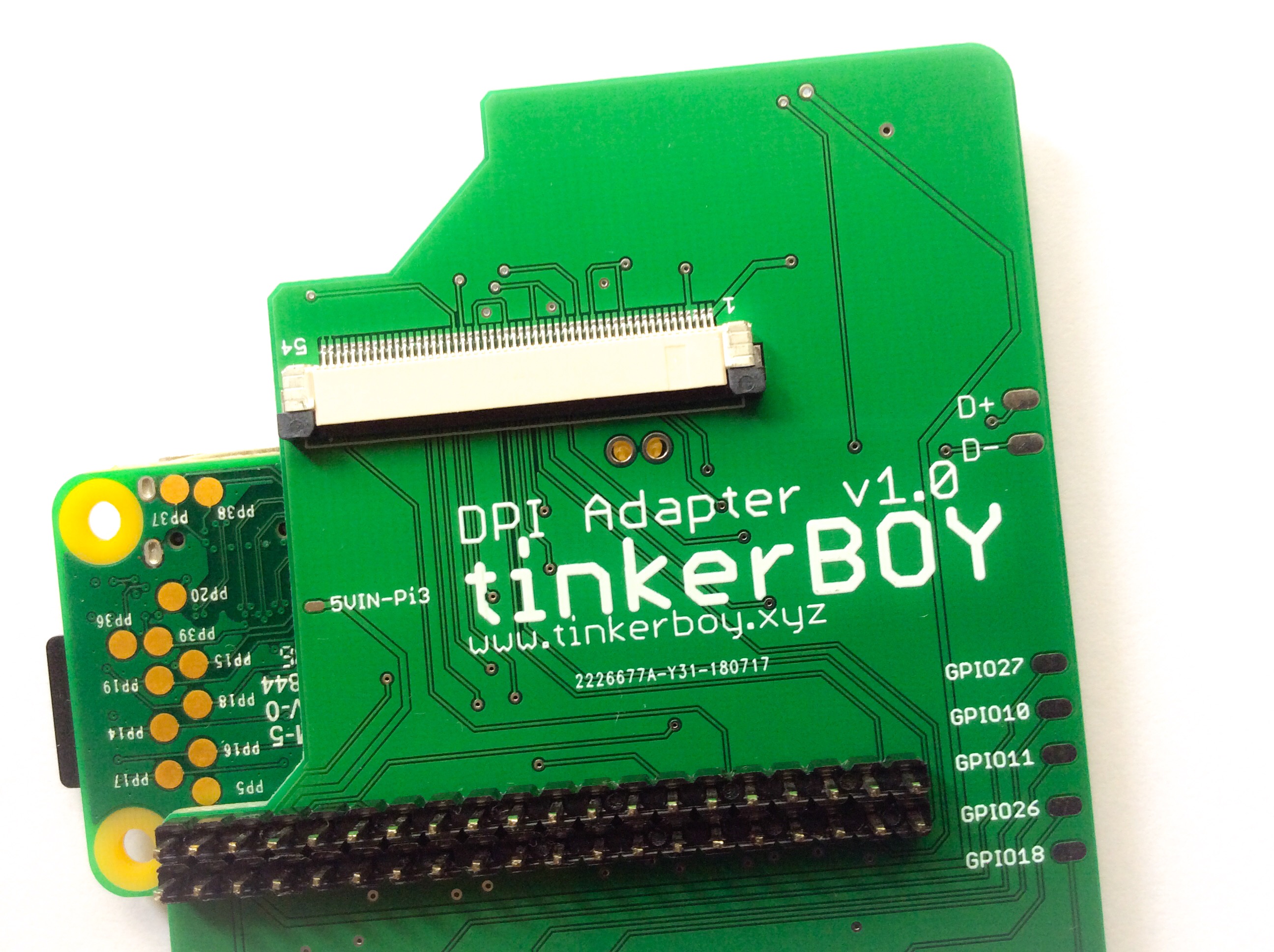
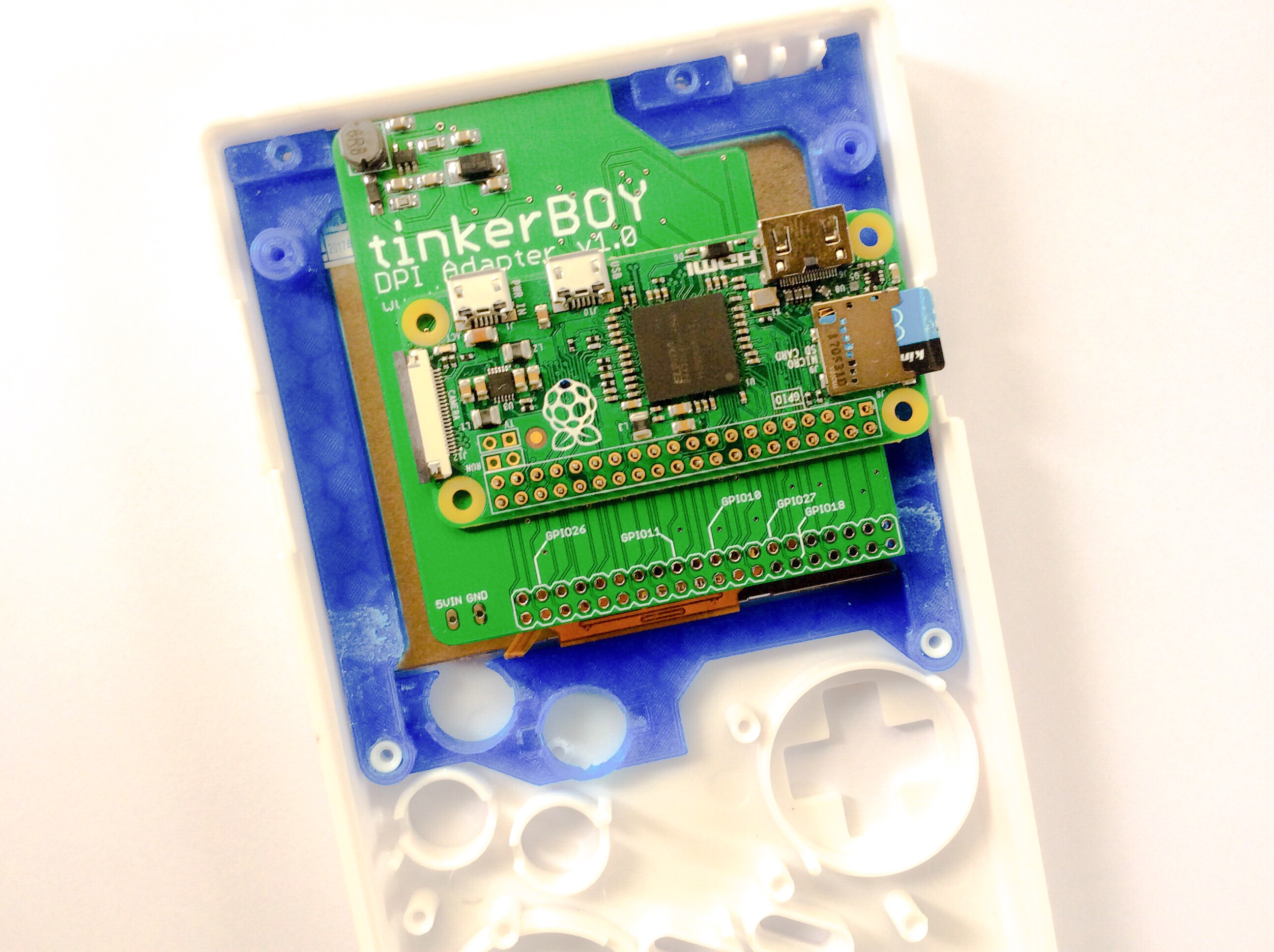
The 5VIN and GND pin holes below the tinkerBOY DPI Adapter are your 5v and GND inputs.
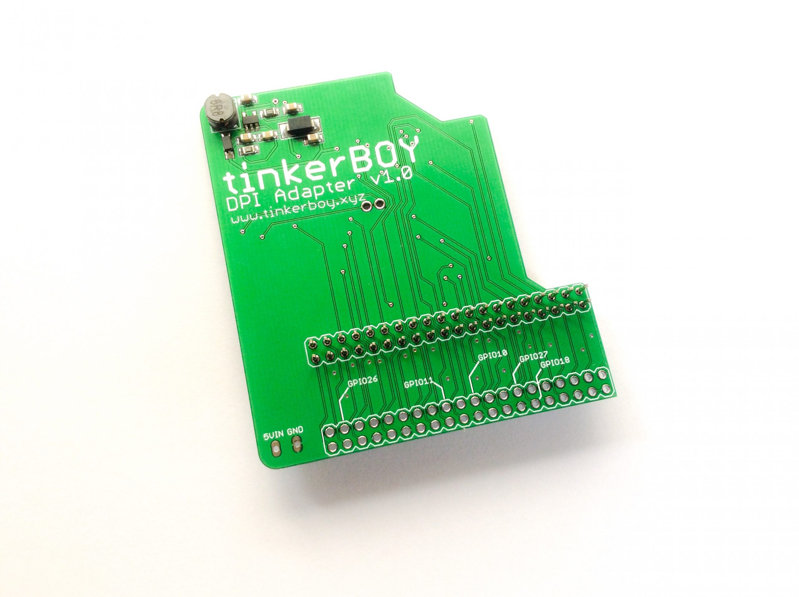
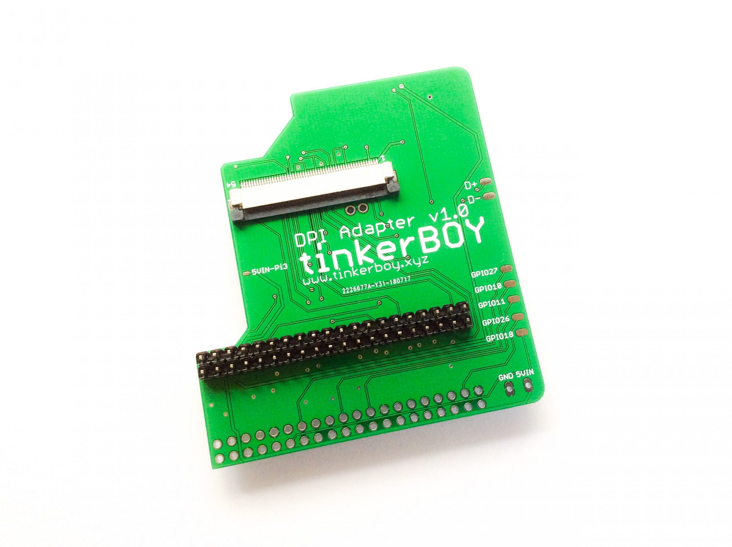
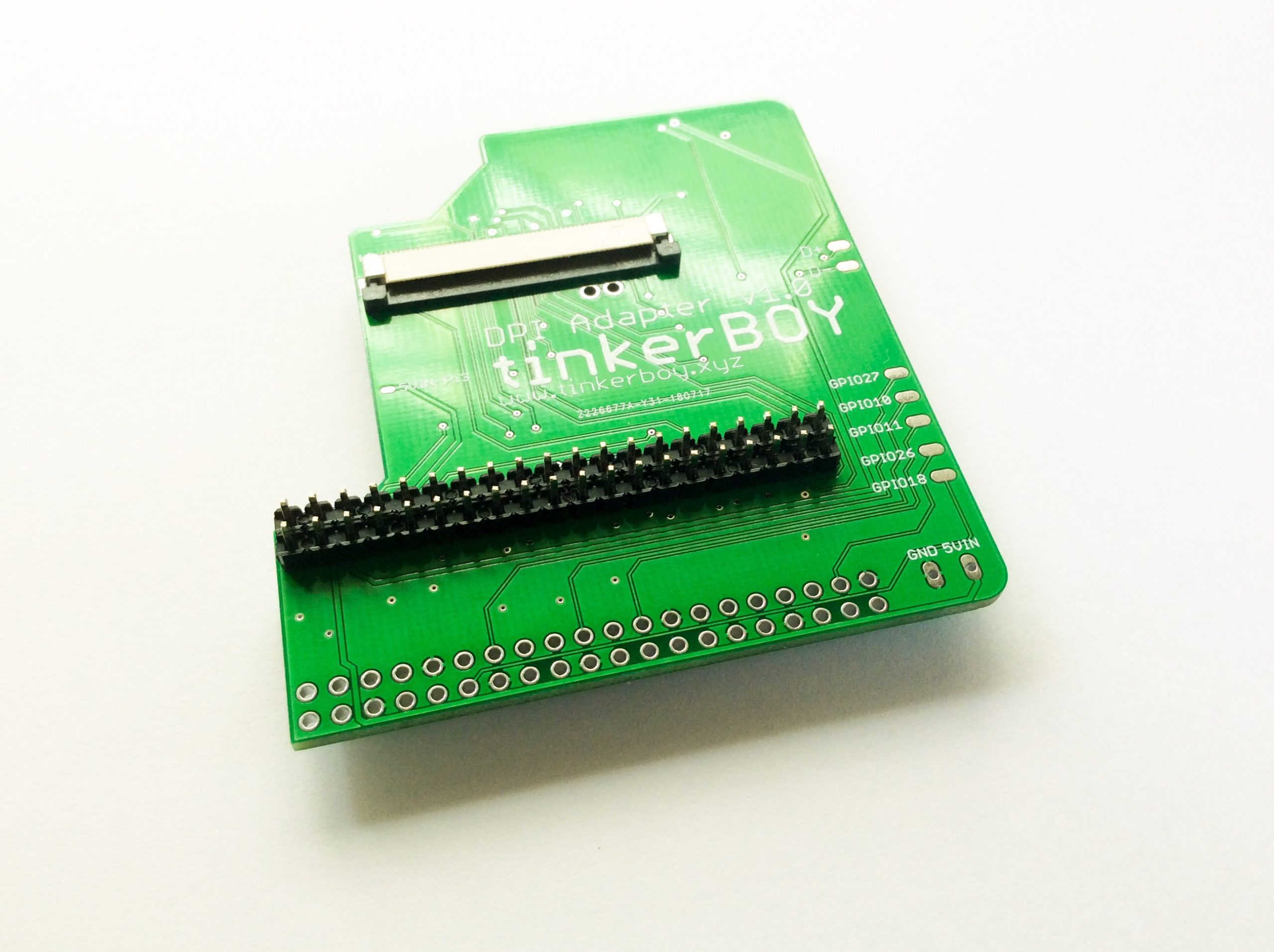
[…] tinkerBOY DPI Adapter v1.0: Visual Guide for Raspberry Pi Zero […]
Hi, how are you?
where do I solder the L1 and R1 buttons, please let me know, thanks a lot.
Have a great one
How to Wire the L and R buttons.
Will gpio controls work with this as well or are there 5 free gpio pins an no more at all?
There are only 5 gpio pins you can use for whatever task you want. So that means it’s not possible to use gpio controllers. The adapter is meant to use with a usb-oriented controller boards like the tinkerBOY Controller v3.0.
So I am not able to use a SafeShutdown board? It requires GPIO 1, 2, 3, 17, 27, 22. If not I will use it in my next build or sell it.
Hi – So I completed a large amount of the wiring and soldering. Now when I plug it in, the screen turns on but nothing is displayed. It’s just blank. Any ideas on what’s wrong or how I should proceed?
Thanks so much!!!
Hi I am following Adambuilds youtube tutorial using a Raspberry Pi Zero W – I’m using your prebuilt Retropie image and when I turn on the gameboy the emulator screen loads but half the screen is just colorful lines and the image quality is really poor, tried replacing the screen with another 3.5 inch back up screen but the exact same issue occurs, is there any advice available on finding the issue?
Make sure each of the pins from the Pi are all soldered properly with their counterpart on the DPI adapter and also make sure there are no shorts.