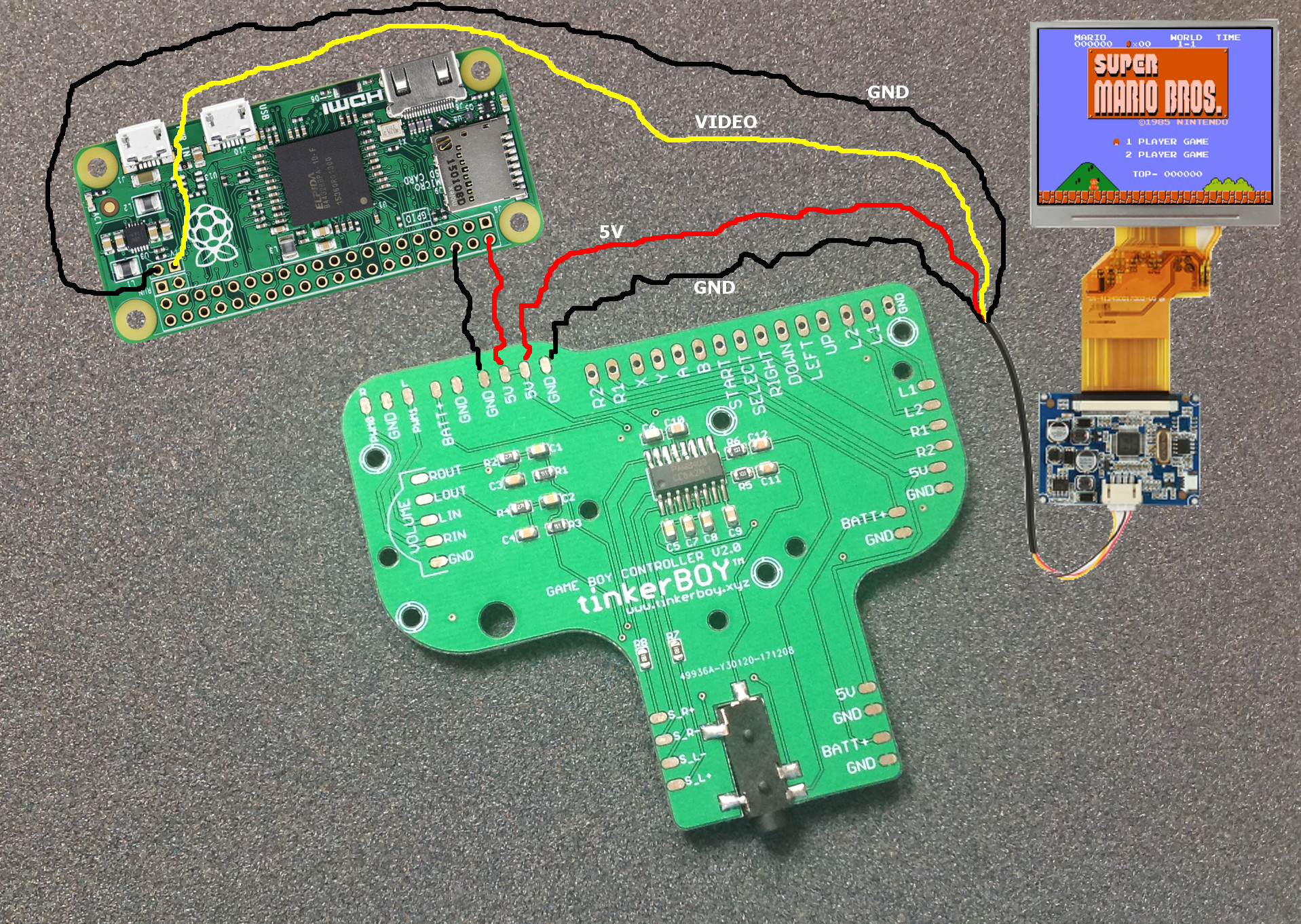
Adding a separate GND wire for the video (yellow wire) is optional but recommended. Diagram assumes you are using a screen that works on 5V power like the GearBest Screen.

Adding a separate GND wire for the video (yellow wire) is optional but recommended. Diagram assumes you are using a screen that works on 5V power like the GearBest Screen.

Hi,
Where does the av1 (white) from the screen go?
How are you connecting a 2nd ground from the screen pcb? Isn’t it common, can I just loop it from where ever?
You can find the screen wiring guide at https://www.tinkerboy.xyz/screen-wiring-guide-for-game-boy-controller-v2-0-v2-1-v1-1/. Just find any common gnd from the pcb screen and connect to any gnd on the board.
Is there a way of controlling the brightness on this screen?
No sorry there’s no way to control screen brightness.
Hello do you know a screen that doesn’t use AV interface?
On my tinkerboard I have only HDMI,MIPI DSI or SPI.
the HDMI screen I use is to gib to feet correctly in the DMG case.
The only hdmi screen i know is the KEDEI 3.5″ screen.
Can you show a wiring diagram for a pi 3b
For pi 3b the yellow or white wire from the screen goes to PP24 on the back side of the pi 3b.