 Below is a modified copy of RetroPie 4.3 image for the Raspberry Pi Zero with built-in support for setting up GPIO buttons using Adafruit’s Retrogame utility program. I have tested it and have been using it for my Game Boy Zero builds.
Raspberry Pi Zero – RetroPie_4.3_GPIO_PiZero.img.7z (578Mb)
Just edit the file /boot/retrogame.cfg to match your GPIO configuration.
Or use the following GPIO soldering setup:
| UP | – | GPIO04 |
| DOWN | – | GPIO17 |
| LEFT | – | GPIO27 |
| RIGHT | – | GPIO22 |
| A | – | GPIO05 |
| B | – | GPIO06 |
| X | – | GPIO19 |
| Y | – | GPIO26 |
| SELECT | – | GPIO20 |
| START | – | GPIO16 |
| L1 | – | GPIO12 |
| R1 | – | GPIO23 |
PWM audio is configured to use GPIO18 and GPIO13 by default but you can edit the following lines in the /boot/config.txt to either enable 1 or 2 audio channel(enabled by default).
# 2 channel audio

dtoverlay=pwm-2chan,pin=18,func=2,pin2=13,func2=4
# 1 channel audio

dtoverlay=pwm,pin=18,func=2
Update: Image file updated to 7z format to shrink the size. Most zip programs can extract it just fine. Otherwise just download 7z.
Products you might be interested with:
-

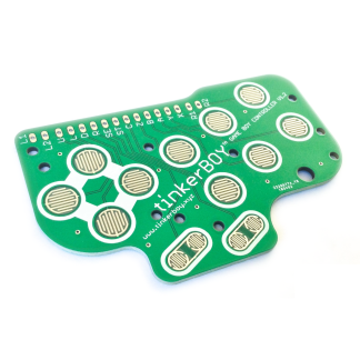
Game Boy Controller v1.2 PCB [6-Button version] for Game Boy Zero / 3
Select options This product has multiple variants. The options may be chosen on the product page -

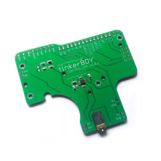
tinkerBOY Controller v2.0.1 for Game Boy Zero
Add to cart -

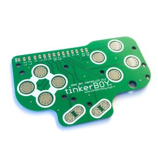
Game Boy Controller v1.1 PCB for Game Boy Zero / 3
Select options This product has multiple variants. The options may be chosen on the product page
[…] can download a copy of RetroPie 4.3 image with the GPIO program already installed and follow the gpio button […]
[…] Wiring the Game Boy Controller v2.0 to the Pi Zero or Pi 3’s GPIO pins is the simplest way to configure controller inputs for the Game Boy Zero/3 without any additional component. You can use the following diagram to solder the button inputs to the Pi and download a copy of RetroPie with the GPIO program already pre-installed. […]
Hello, I’m having trouble with the audio I have successfully soldered it the way you posted your image for the audio but still no sound I have checked the sound o the speaker it works great. But no luck with sound
No sound with from headphone jack or just from the speaker? Can you post some pictures of your build? Will help a lot in troubleshooting.
What controller board are you using? Pi Zero or Pi 3?
Make sure you are using the correct GPIO map: https://cdn-learn.adafruit.com/assets/assets/000/037/733/medium800/gaming_New-GPIO-Diagram.png?1480813804
I’ve just completed my first gameboy zero build using a RPI zero.. I soldered all of the wires to the Pi following the wiring diagram above and also properly burned the above retropi 4.3 image with GPIO button support and when I turned it on to test it everything worked as expected except my “down” button and my “X” button. All other buttons work fine though. Any ideas on what I should try?
Connect to your Pi Zero via SSH and enter the following command to test the Retrogame Utility.
sudo /usr/local/bin/retrogameYou should get a response on the screen when you press each button. Otherwise make sure the non-responsive is soldered properly. You can easily verify this with a digital multimeter.
Thank you, I will test it out with my digital multimeter and will re-solder the 2 non-responsive buttons’ wires. Thank you for your quick response, and I wanted to say how much I appreciate the retropi 4.3 download with the GPIO button support that you made, it makes my life a whole lot easier!
And I love that awesome screen that says “Gameboy Zero” on boot-up 👍
I wanted to really give this a try. It seems like it does everything I want it to. Use the GPIO AND stereo audio all through RetroPie. It’s the only thing I’ve come across that seems like it will work for my project. However, after downloading, it unzips fine, but I’ve tried 2 ISO programs (MagicISO and WinISO) to unpack the ISO and they both said it was not readable. I redownloaded again just incase and the same thing. I tried both Winrar and 7Zip when unzipping, so I’m not sure what’s going on, or if I am even supposed to use an ISO program with the ISO. There was no instructions on that part. Any help would be appreciated. Thanks!
Unzip it with 7zip and write the image to a sdcard using Win32 Disk Imager.
Oh right, it’s been a while since I’ve had to use that program. Thanks for the friendly reminder and the quick response. And also thanks for all this too. I sure hope this works out. I’ve been searching for the right software combo for my portable Retropie and this is looks to be exactly what I am looking for.
I have purchased a tinker boy v1.1, and looking at the GPIO soldering setup you have it does not have the L2 &R2 location that I could see. What would be recommended location to solder these on the GPIO on the zero?
First time trying to make one of these and still trying to learn everything. Thanks for the help
Ryan
Reporting back and it works like a charm! Thank you for going through all this trouble for us, and I love the fact it makes the resolution on the Composite bigger so you can actually read the text. One last question. On my setup, I included a hotkey. It worked on my last setup, so I know it’s wired up correctly, but when setting up the controls, it wouldn’t detect it. I have it wired up to Pin 18, BCM24. Is there some configuring I need to do for it to be able to use it, or should I wire it up to another BCM port that it can already use without having to go in a reconfigure. Thanks!
Hello again, I just bought a “6 button” PCB to make another gameboy zero and I was wondering how I would go about wiring the 2 extra buttons “C” and “Z”? I would also like to know how to wire the “L2” and “R2” buttons. I have successfully built a gameboy zero with the standard “4 button” PCB that has (up, down, left, right, start, select, A, B, X, Y, L, and R) buttons, but now I’m looking to add “L2, R2” and the extra “C” and “Z” buttons. Any help would be greatly appreciated! Thank you
i have the same question
When I download this image on my Mac, and try using etcher, it is grayed out and says it is not a supported image. What am I doing wrong?
You have to extract the file first.
I’ve just completed my first gameboy zero build using a RPI zero.. I soldered all of the wires to the Pi following the wiring diagram above and also properly burned the above retropi 4.3 image with GPIO button support and when I turned it on to test it. it wont worked . All buttons work fine with a digital multimeter. Any ideas on what I should try?
You have to configure the inputs in RetroPie menu before using the buttons.
can you give me more info in mail how to do it .
Same here, all wired up, but when I launch this image, it says “No gamepad detected” and thats it, I need help! 🙁 No sound is wired, just the controls except L1 and R1, will be done this afternoon. Any advice? Thanks a lot.
It looks similar to this thread at https://sudomod.com/forum/viewtopic.php?f=44&t=6206.
i have download the new 4.4 retro pi and install retrogame.and config. my buttons and all work fine now.
only the sound is not so good
Was hoping this prebuilt retropie could help get my controller working but it hasn’t 🙁 It doesn’t detect my buttons at all, wired up as per the diagram. They work in other version I’ve etched to the SD card though not all of them work, hence why I’m looking for other solutions.
Not sure what I’m missing but I can’t even run the sudo /usr/local/bin/retrogame to test it out. Nothing in the bin folder at all…?
Try another sdcard and let me knwo.
ok so i got the config file the six bt one and put it in the root folder but when retropie takes me to the controller setup nothing happens, what am i missing?
Hello,
i recently wireed up all my wires to the GPIO but when i go into the retropie files i cannot find that retrogame.cfg file.
i am using ubuntu as my linux software to access the files. do i just have to make a new file or is there another way to find the file?