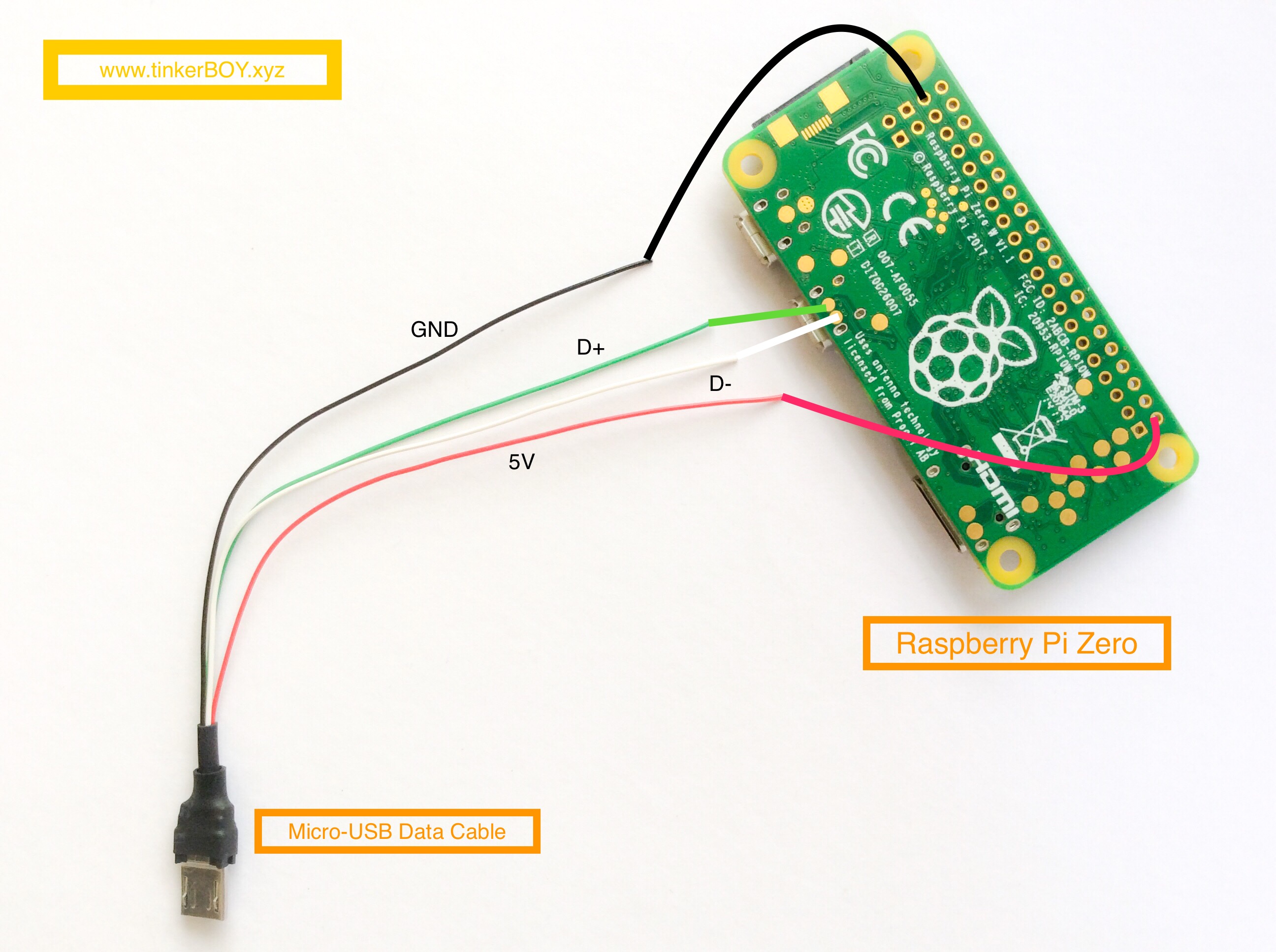
Connecting the Micro USB 4-Wire Data Cable to the Pi is pretty straightforward.
- Black wire connects to any GND pad.
- Red wire connects to any 5V pad.
- Green wire connects to the D+ USB pad.
- White wire connects to the D- USB pad.

Connecting the Micro USB 4-Wire Data Cable to the Pi is pretty straightforward.

[…] >> How To Wire The Micro USB 4-Wire Data Cable. […]
Hello I just received your controller board v2.2 and the µusb port was a little bit inclinate down.
after diffilculties to plug in the usb cable in order to program the chip with the arduino IDE I decide to unplug the cable and now the female connector is totally unsoldered.
is it a way to fix it or the pro micro is dead?
is it possible to change it anyway or must I trash all the board?
You must have forcefully plugged an unstripped micro USB cable? Try soldering the data wires directly to the pro micro but those pins are very tiny.
Yes my bad :/ I was too impatient to begin to enable the stick in your microprogram.
for the cost isn’t simplier to takeoff the pro micro and replace it by a new one?
how did you do to place it on the controller? only glue?
An other not related question, are you working with asus tinker board SBC?
maybe could we continue this passionate discussion in private?
Best regards
Hello,
I am building a GB Zero using the v2.2 controller board I purchased from you. Since I do not have experience in implementing the Pro Micro as a controller, my question is: what is the purpose of this cable? Is it for accessing the Pro Micro via the micro USB port on the Pi Zero for the purpose of programming? Or is it for functionality of the Pro Micro with the Pi Zero?
Thanks.
I just made this cable for easily connecting the board to a Raspberry Pi although you can also do it by stripping a microusb data charging cable if you have one.
Thanks. I made a microusb data cable and checked the wiring after soldering as per diagram. The controller on the tinkerboy is still not recognized. I noticed that the power led is on solid but the Rx and Tx leds are off. After reboot, Retropie gives a message ‘Cannot open access to console, the root account is locked’. Please let me know if you have any suggestions on how to fix this. Thanks again.
Looks like you might have a corrupted sdcard. Try a new installation. The tx and rx LED will not come on if it’s not properly recognized by the host system. You can test it first on a Windows pc.
Is the process any different when using a raspberry pi 3? Can you possibly make a wiring guide for the pi 3? Thanks in advance