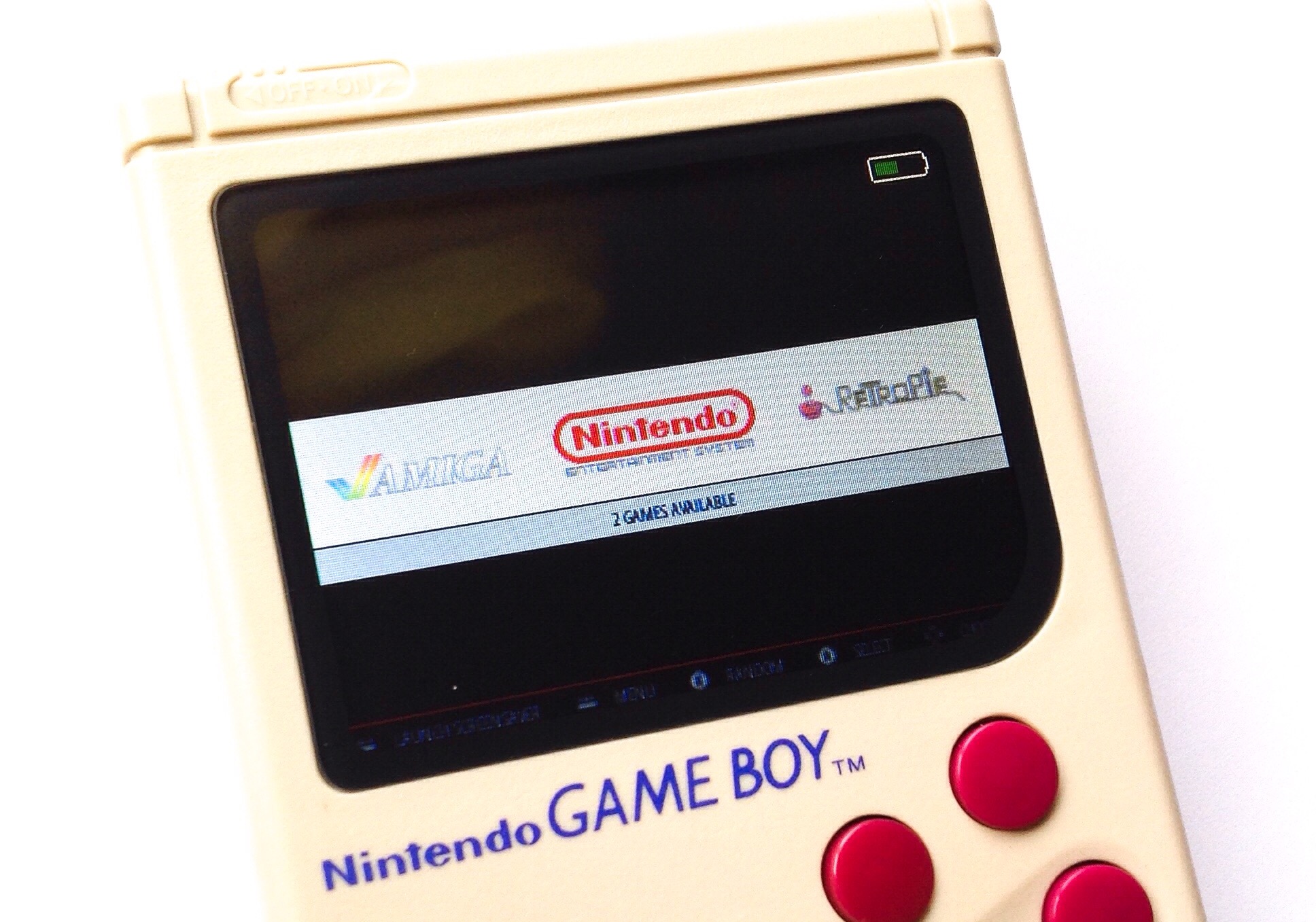
This tutorial is covers the steps on how to enable battery monitoring for the tinkerBOY Controller v3. Make sure your v3 is plugged in or connected to your Raspberry Pi before setting up the Battery Monitoring service.
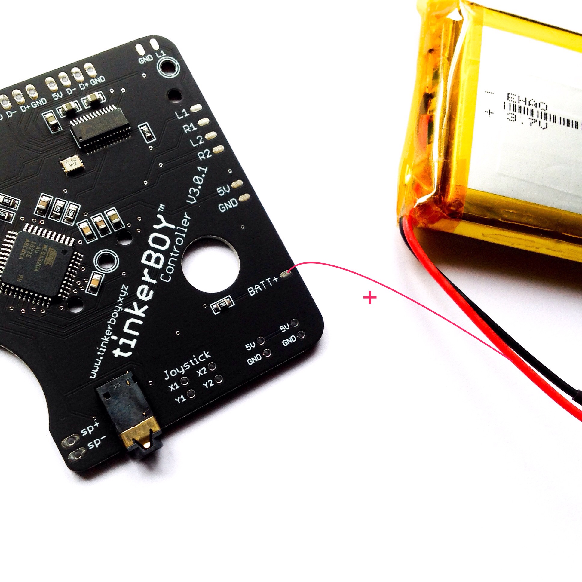
Step 1. BATT+ to battery’s positive wire.
Solder a wire from the BATT+ pin on the v3 to the positive wire(red) of the battery.

Step 2. Setup the battery monitoring script.
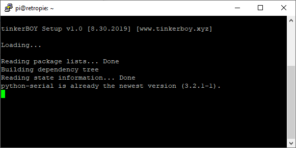
Login to your Pi via SSH and type the following command:
wget -O - https://www.tinkerboy.xyz/setup.php -q | bash -s bm
It will install the necessary software for the battery monitoring service. It will also upgrade your v3’s firmware if needed.

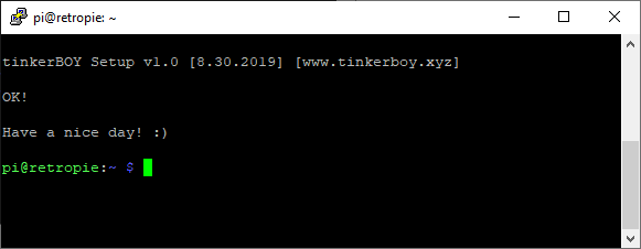
When it’s done you should get an “OK!” message if it’s successful. Otherwise, let me know when you get an error.

Step 3. Enable the Battery Monitoring service.
Type or copy paste the following commands:
sudo systemctl daemon-reloadsudo systemctl enable battmon.servicesudo systemctl start battmon.service
Issuing these commands will immediately start the Battery Monitoring service.
That’s it. Have a nice day! 🙂
[…] Battery Monitoring for tinkerBOY Controller v3. […]
As I’m a newbie in electronics, this is not crystal clear to me, so, sorry if it’s a dumb question.
Do I need to wire it normally THEN add another wire to this BATT+ pad, or do I need to wire my red wire to this pad instead of 5V ?
Looks like a good addition, thank you for that 🙂
I figured it myself. If you’re wondering too, the answer is : wire it normally, then add another wire from BATT+ on the Tinkerboy’s V3 to the red wire on your battery.
works, thanks!
Tinkerboy – how do we change the size and location of the battery icon once installed?
I might do a separate tutorial on how to do that.
any tips on how to fix it? when i followed these instructions it worked but the battery icon is very small. thanks
If I plan to use a JST connection to plug and play the battery to the Add on power boost switch, do I just expose a spot on the red wire mid way through and solder it to that? Or do i solder the BATT+ pad to the Add on power switch pad where the Battery JST connection wires attach?
Just solder it directly to the PowerSwitch so you don’t end up exposing the battery wire.
Would I be able to just solder the 2nd BATT + wire to the power switch and then to the v3 board? I plan on using both in my build and wanna know before buying everything.
Never mind, I see the comment stating just that solution.
✓
Would this work on the Rpi 4 if I were to use the method of installing RetroPie on the Rpi 4 which was in a video by ETA Prime? So if I install retropie onto Rpi 4 through Raspbian and take the same steps.
Nevermind, so first of all, the method used in ETA did not work so I found another work around to install RetroPie onto Rpi 4. After installing, I have tried the virous scripts used to get the V3 controlelr board and it works all goods.
Hello! Would you mind sharing which scripts you used to get the v3 controller board working on Rpi4? Thanks!
How can i use this script in order to monitor my battery if i have the powerswitch with the safe shutdown script? How do i wire it now? Can i wire the “p” and “s” to the gpio10 and the gpio11 of the dpi adapter instead of the pi gpio? Cause those holes are soldered with the dpi adapter.
The instructions can seen at https://www.tinkerboy.xyz/setup-and-wiring-guide-for-the-tinkerboy-powerswitch/