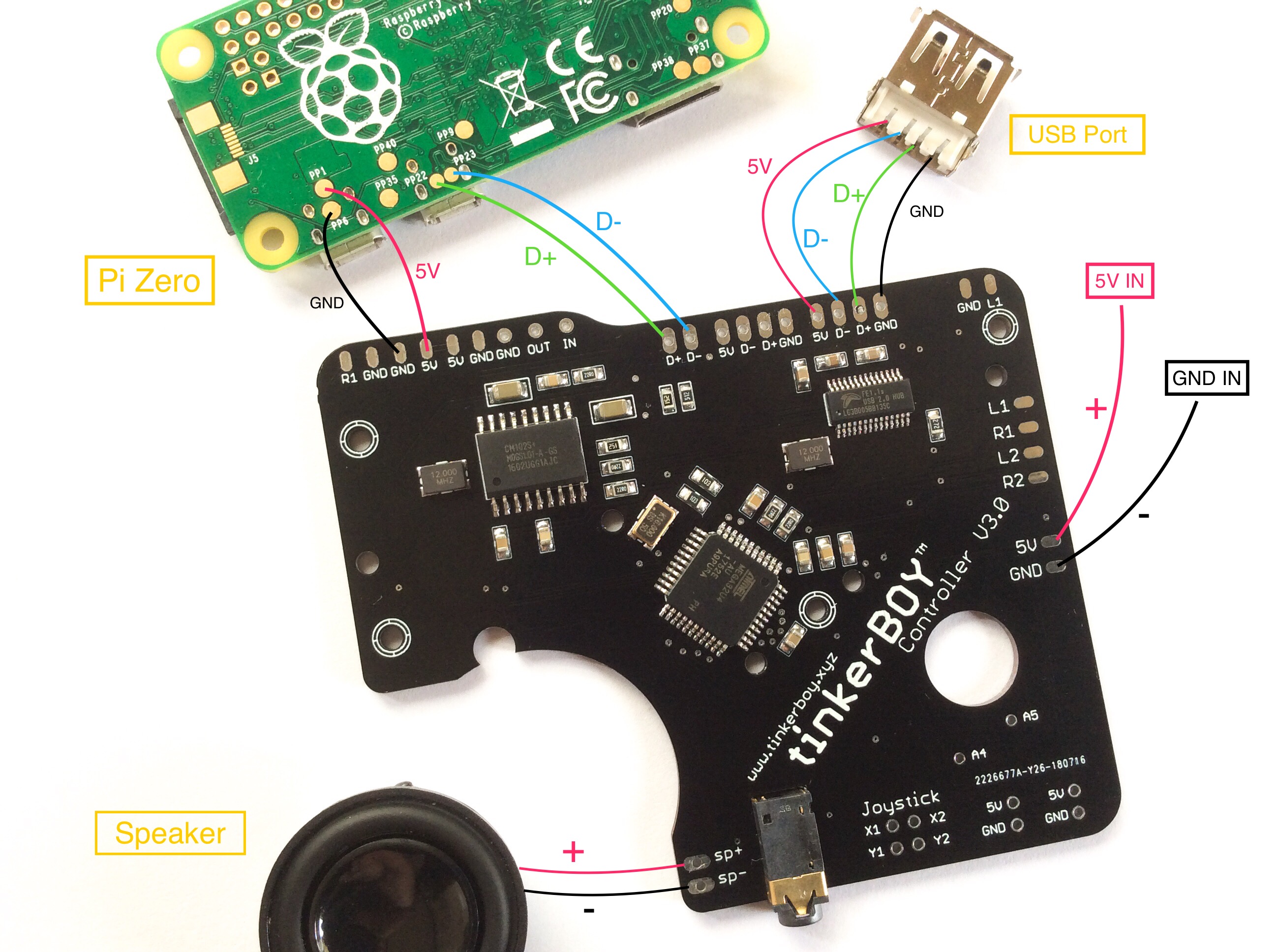
Pi Zero:

For the Pi 3 just wire the data pins to the corresponding pins on the v3 controller board. Here’s how you power the Pi 3.
Pi Zero:

For the Pi 3 just wire the data pins to the corresponding pins on the v3 controller board. Here’s how you power the Pi 3.
[…] Wiring Diagram for tinkerBOY Controller V3.0 […]
Hi, what are the data pin numbers on the raspberry pi 3 a+? Many thanks.
[…] you’ve already followed the wiring guide and connected your v3.0 board to a Raspberry Pi, login via SSH or connect a keyboard and hit F4 to […]
Hi There,
I am new to all of this, so just trying to wrap my head around things, looking at your board, and wiring diagram why would I need to put a USB port on to the board? What purpose is that for.
I am also assuming I would still need a powerboost board also?
The USB port is optional but it’s great to have external port so you can connect devices like keyboard or another usb controller if you want to play with your friends. Like this one:
Ah see now that makes sense 🙂 Many thanks, another quick question again I am new to electronics and just wrapping my head around stuff.
In the diagram you 5v in and GND in am I correct in assuming that, would go to the powerboost?
Yes that’s correct. Sorry I missed that on your previous comment.
Again many thanks for your help, I will be purchasing this controller shortly, I just wanted to get everything right, what was needed and that I would wire it right.
Again thanks for help.
maybe a charge circuit with 3.7V battery connector for the v4.0? :p
Maybe. 🙂
I was going to put header pins on the 3.0 board wherever possible, and use wires with connectors, to keep this very modular. I’m still waiting for my physical board to get in, but looking at the pictures, it appears like the 5V and GND inputs are surface mount. (I’m not sure if I’m skilled enough to surface mount a header pin. I can solder a wire directly to it, if I have to.). Can this board be powered at any other points? Could I drill mounting holes in the board?
Yes you can power it from any 5v/GND on the board. No you cannot drill any holes on the board. you’ll damage it. 🙂
Hello, just received my 3.0.1 board and wired it the same as your diagram using a Pi Zero but I’m getting no gamepad detected when retropie booted up. Any ideas on how to fix this?
Did you start from a fresh intall of RetroPie? Did you test the Pi Zero’s USB port before soldering the v3.0?
hey tinkerboy,
i wired everything as shown on the diagramm. but I have no sound 🙁 do I have to install something else
You have to setup usb audio as the default sound device. It’s there on https://www.tinkerboy.xyz/getting-started-guide-for-tinkerboy-controller-v3-0/.
Hi, how are you?
sorry I think I posted this on the wrong page before, but please could you let me know where do I solder the L1 and R1 buttons? (I’m using the new display board v1 ) any help will be more appreciated, thanks a lot
How to Wire the L and R buttons.
How would I go about charging an internal Lipo battery with this AIO board?
You can use the Adafruit Powerboost 1000c for both charging and 5v boosting.
Hey TinkerBoy! Thanks for making amazing easy to use products you’re a homebrew life saver! I’m just getting a little confused with some of the info. I really want to level it up and make a GB0 with a pi 3 b+ so I can finally play a lot more n64 roms. Anyway from what I understand in your pics if I use a pi3b+ could I just wire it to your v3 controller the way you have depicted here, and then follow the rest of your diagrams as if it was a pi zero? For example I could just attach the gearbest power boost to the 5v and ground where you have it in the first picture or would I need to use the adafruit? sorry so many questions
It does not matter which 5v boost module you use whether the Adafruit Powerboost 1000c or Gearbest Powerboost. All should work fine depending on how much power you’re using. Both can have a 1A output limit which should work on most build.
The board looks great!
Is it possible to reprogram the Atmega32u4 used as an input controller? If yes, is the controller code open source? Does it use a custom bootloader?
I would like to build a GBZ, mostly for the fun of building it. During the process, I want to understand every part of it, play with the settings and experiment. This board seems like a great starting point, since it provides most of the hardware parts in a compact, elegant form. I am just wondering how much we can customize it, especially the software parts.
Does not use any custom bootloader but just the Arduino Leonardo bootloader. And yes you can reprogram the atmega32u4 either via USB or ISP. The code is almost the same as the code i published at https://www.tinkerboy.xyz/arduino-usb-gamepad/.
Hello there.
This is a life saver if you don’t have any or little soldering skills 😭, which is my case.
I am considering to buy this for my own project. A Gameboy with a 5 inch monitor.
It is going to be a bit bigger then the Gameboy case, but it might be doable. Still trying to get it done on 3D.
My question here is, my soldering skills are very limited, is this something doable for someone like me. And if so, I just follow this guide that you have and it’s a wrap?
Thank you very much for your attention
Rodrigo
Yes i think so. It’s absolutely doable for beginners with limited soldering skill. But would practice a little soldering and watch YouTube videos about it.
Hi,
Would It Be possible to add a battery monitor script on the atmega?
You can create a python script on the Pi side and just send a serial command ‘9’ and the v3 board will reply with a raw analog reading of the battery provided you connected the BATT+ to the battery’s positive pin.
Hi! I just received my v3.0.1 today. I notice you have a BATT + pad at the bottom right, which doesn’t appear on the v3.0. I’m new to all this, so forgive my ignorance. Should I still run the battery into the 5V and GND above this, per your wiring instructions for the v3.0? If so, just out of curiosity, what’s the purpose of the BATT + pad? Also, are there any notable changes from 3.0 to 3.0.1? Thanks for your help. I’m looking forward to getting started!
Blessings!
BATT+ is for connecting the positive of the battery for monitoring if you want to do a script on the Pi side. 5v and gnd is for 5v and gnd output of any Powerboost.
V3.0 and v3.0.1 are basically the same with the exception of the BATT+ but you can easily do that on a v3.0 too.
Thanks very much! So, if I understand correctly, if I wanted to monitor the battery via script from the Pi side, I would connect the battery power to the PowerBoost and also to the BATT+? Thanks again for your time! I’m learning a lot through this. It’s a blast!
Hello, I just put an order in for the 3.0 controller board. Does this include safe shut down or do I need to purchase something else to go along with this board? Or is it just done by a script.
Also I have a bunch of Gearbest Powerboost boards, I’m assuming these will work with this board or if it is required?
Thanks and looking forward to receiving the boards!
You need to get a separate module for the safe shutdown. It’s a combination of hardware and script. I’m actually working on my PowerSwitch v1.0 to implement this feature.
For all my controller boards, you need boost and charger module like the Powerboost 1000c or GearBest PowerBoost.
Ciao, ho appena ricevuto la mia scheda 3.0.1 e l’ho cablata come il tuo diagramma usando un Pi Zero w, ma non ricevo alcun gamepad rilevato quando retropie è stato avviato. ho installato il retropie configurato da te come consigliato ma non funziona helpppp
Che immagine stai usando? tinkerboy retropie?
controllare la saldatura 🙂
ciao ho usato il tuo retropie configurato per tinkerboy v3.0.1 ma mi dice gamepad non presente controllato tutte le saldature e sono ok .
come posso fare
Check your wiring on the data pins if it’s not being detected by your Raspberry Pi.
Hi,
so I can connect 2 additional USB port on the board right ? They will both be detected as independent ports ?
Thank you very much !
If I wired the adafruit power boost to the aio pub, then from there would it power the pi itself, or would I have to figure out another way to more directly power the pi? Also, how do you wire the tinkerboy volume wheel add-on board to this version 3 aio board? Thanks!
Hi everyone,
I need your help and it is always displayed that no gamepads detected. Maybe you can see something in the picture.
thanks
https://i.imgur.com/H04VQQH.jpg
ok i found it, it was a soldering place
Hi, Any chance you could provide an updated wiring diagram for the Pi 0 2 w? I’ve been having issues getting the board to work with it and I figure I must be doing something wrong.
Do I need to purchase wires separately or does it come with wires.
You need your own wires of course. 🙂